
Introduction


In the highly deterministic, zero-tolerance environment of automated manufacturing, electrical instability is the silent architect of catastrophic system failure. When an industrial facility experiences a localized voltage sag lasting a mere 20 milliseconds, unprotected logic controllers instantly crash, triggering massive data corruption and complete robotic cell paralysis. To mathematically eradicate these profound electrical vulnerabilities, executing rigorous industrial power supply selection is the absolute foundational mandate for any control systems engineer. A power supply is not merely a passive voltage converter; it is the primary defensive firewall protecting millions of dollars of sensitive silicon microprocessors from the violent electrical realities of the factory floor.
Historically, panel builders frequently undervalued this critical component, attempting to reduce capital expenditures by installing commercial-grade, unregulated power bricks. This fundamental miscalculation guarantees systemic failure. Heavy industrial environments are saturated with massive inductive loads—such as 500-horsepower compressor motors and high-voltage welding transformers. When these loads actuate, they generate immense inrush currents that physically drag down the localized AC mains voltage, creating severe brownouts. Simultaneously, they inject high-frequency harmonic distortion back into the grid, which violently degrades the delicate DC circuits powering PLC hardware and remote sensing arrays.
To secure operational dominance, electrical engineers must migrate their panel architectures to high-performance, harmonically suppressed power conversion topologies. This comprehensive B2B technical manual aggressively deconstructs the internal physics of Switched-Mode Power Supplies (SMPS), evaluates the rigorous thermodynamic parameters required for DIN rail installations, and details exactly how partnering with a verified automation component supplier permanently guarantees absolute voltage stability across your entire critical infrastructure.
The Physics of Switching Power Supplies & Harmonic Suppression

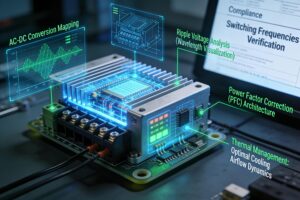
To objectively execute a zero-fault electrical integration, engineers must deeply analyze the precise physics governing modern AC-DC inversion. Legacy linear power supplies relied on massive, highly inefficient iron-core transformers that dissipated enormous amounts of energy as heat. Conversely, modern DIN rail power modules utilize advanced Switched-Mode Power Supply (SMPS) architectures. An SMPS immediately rectifies the incoming 120V/240V AC mains into a high-voltage DC bus. This DC voltage is then mathematically ‘chopped’ by high-velocity MOSFETs switching at frequencies between 50 kHz and 100 kHz. This high-frequency pulse is pushed through a highly miniaturized ferrite-core transformer, stepping down the voltage, before being meticulously rectified and filtered into a perfectly stable 24V DC output.
A critical engineering specification during this conversion is Ripple Voltage, mathematically expressed as millivolts peak-to-peak (mVpp). High-quality industrial supplies guarantee a ripple voltage of less than 50mVpp. If a substandard power supply allows excessive AC ripple to bleed into the DC output, the highly sensitive analog-to-digital converters within your industrial sensor networks will register constant fluctuation, completely destroying the accuracy of pressure and temperature telemetry.
Furthermore, modern power regulations demand absolute grid efficiency. Advanced industrial power supplies deploy Active Power Factor Correction (PFC) circuitry. Non-PFC supplies draw current in sharp, highly destructive spikes, generating massive harmonic distortion that overheats neutral wires and trips facility circuit breakers. Active PFC utilizes a dedicated boost converter to mathematically align the input current waveform perfectly with the input voltage waveform, achieving a Power Factor (PF) of 0.99. This guarantees that the facility draws only the exact active power required from the grid, completely eliminating reactive power waste and ensuring absolute compliance with stringent international harmonic standards.
Ensuring Power Reliability in China’s West-to-East Power Transmission Hubs
The strategic deployment of robust power conversion architecture is aggressively dictated by the scale of the facility’s localized energy demands. Consider the massive industrial expansion within Guizhou, China. As a critical anchor in China’s monumental ‘West-to-East Power Transmission’ infrastructure, Guizhou hosts some of the most advanced, high-density big data centers and heavy metallurgical smelting operations on the globe. Consequently, while the macro-grid possesses immense generating capacity, the localized industrial micro-grids are subjected to unprecedented inductive stress. Therefore, when a massive smelting furnace initiates its arc cycle, the localized line voltage experiences violent, instantaneous sags.
Furthermore, facility engineers managing the automated material handling systems in these zones cannot rely on the raw mains power to sustain their critical logic networks. Consequently, they strictly mandate the deployment of ultra-high-reliability 24V DC power supplies. Therefore, these specific power modules are engineered with massive internal electrolytic capacitor banks designed to provide a minimum ‘Hold-Up Time’ of 20 to 30 milliseconds under full dynamic load. Consequently, if the localized AC grid drops out entirely due to a heavy inductive startup on an adjacent assembly line, the power supply’s internal capacitors mathematically bridge the temporal gap, sustaining a flawless 24V DC output to the PLC until the AC mains recover.
Furthermore, these advanced manufacturing hubs utilize sophisticated Redundancy Modules to eliminate single points of failure. Consequently, engineers wire two identical power supplies in parallel through a dedicated diode OR-ing module. Therefore, if Primary Supply A suffers a catastrophic internal component failure, the diode module instantaneously shifts the entire facility’s logic load to Backup Supply B with zero millisecond interruption. Consequently, this proprietary electrical architecture completely isolates the facility’s production velocity from both external grid anomalies and internal hardware degradation, ensuring continuous, high-margin manufacturing throughput.
Comparison Matrix: Industrial Power Topologies
To objectively evaluate the structural and financial viability of varying power conversion architectures, electrical engineers must critically analyze comparative integration data. The following matrix mathematically contrasts core power topologies based on input phasing, operational redundancy, and ideal industrial deployment:
| Power Architecture | Input Phase & Voltage Stability | Operational Uptime & Fault Tolerance | Optimal Industrial Application |
| Single-Phase SMPS (120/240V AC) | Standard. Draws from a single AC line; susceptible to localized phase dropping. | High. Excellent MTBF, but zero redundancy if internal components fail. | Localized control panels, standalone OEM machinery, and edge I/O racks. |
| Three-Phase SMPS (400/480V AC) | Supreme. Mathematically balances the load across all three electrical phases. | Extremely High. Capable of operating at reduced capacity even if one AC phase drops (2-phase operation). | Massive motor control centers, high-amperage CNC cabinets, and heavy continuous processing. |
| 1+1 Redundant Configuration (Diode OR-ing) | Variable (Depends on input sources). Often utilizes completely separate mains feeds. | Absolute. Mathematical guarantee of zero downtime upon individual supply failure. | Critical SCADA servers, pharmaceutical batching, and continuous petrochemical refining. |
| Uninterruptible Power Supply (DC-UPS) | Absolute. Integrates a dedicated 24V battery bank into the DC bus architecture. | Supreme. Provides minutes to hours of logic power during total facility blackouts. | Safety shutdown sequences, data logging retention, and critical emergency evacuation protocols. |
Installation Best Practices & Thermal Specs
Executing a structurally flawless power integration requires absolute adherence to rigorous thermodynamic parameters. Industrial power supplies are predominantly passively cooled, relying entirely on the physics of natural convection. As internal components generate heat, the hot air rises and exhausts through the top vents, drawing cool air through the bottom. If an engineer violently restricts this airflow by mounting wire ducts or massive servo drives directly flush against the supply, the unit will instantly suffocate. Best engineering practices dictate a strict minimum clearance of 50mm above and below the unit, and 15mm laterally, ensuring the thermodynamic convection cycle remains unbroken.
Furthermore, engineers must meticulously calculate the module’s Thermal Derating Curve. A power supply may be rated for 20 Amps at 40°C. However, inside a sealed, unventilated control cabinet baking on a factory floor, the ambient temperature can easily exceed 60°C. According to the derating curve, at 60°C, the physical output capacity mathematically drops to 15 Amps to prevent the silicon from incinerating. If the engineer failed to calculate this thermal derating and consistently draws 18 Amps, the supply will continuously trip its internal thermal overload protection, paralyzing the attached automation network.
Finally, output protection dynamics must be evaluated. When a field sensor wire is physically crushed and shorts to ground, the power supply must protect itself. Advanced units feature ‘Hiccup Mode’ short-circuit protection. Upon detecting a dead short, the supply instantly kills the 24V output, waits two seconds, and ‘hiccups’ (attempts to restart). It continues this mathematical loop indefinitely until the short is cleared, preventing the internal coils from melting. By adhering to these strict thermal and electrical protocols, supported by verified components from Enicstra, technicians guarantee absolute control circuit stability.
Frequently Asked Questions (FAQ)
- Can I wire two standard 24V DC power supplies in parallel to double my available amperage?
Do not wire standard supplies in parallel unless they specifically feature a ‘Parallel Use’ switch or current-sharing circuitry. Because no two supplies output exactly 24.00V, the supply with the slightly higher voltage will mathematically attempt to carry the entire load, instantly overloading itself while the secondary supply sits idle. Parallel operation requires specialized active load-sharing architecture.
- What is the mathematical definition of MTBF, and how is it calculated for power supplies?
Mean Time Between Failures (MTBF) is a statistical calculation defining the reliability of a component, not its guaranteed lifespan. It is calculated utilizing rigorous standards like MIL-HDBK-217F or SN 29500, assessing the failure rate of every individual internal capacitor and resistor at a specific temperature (usually 40°C). A higher MTBF strictly indicates a lower statistical probability of failure within the intended operational timeframe.
- How do I properly size a power supply based on the combined wattage of my components?
You must calculate the aggregate maximum current draw of your PLC CPU, all I/O cards, HMI panels, and field sensors. Once you calculate the total required amperage, multiply by 24V to find the base wattage. Standard engineering practice dictates sizing the power supply at 125% to 150% of this calculated base load to account for high-inrush startup currents and to prevent operating the supply constantly at its maximum thermal limit.
- What does a NEC Class 2 rating indicate on an industrial power supply?
The National Electrical Code (NEC) Class 2 standard strictly dictates that the power supply’s output must be inherently limited to 100 Volt-Amps (roughly 4 Amps at 24V DC) and completely isolated. This mathematical limitation ensures that even in a dead-short scenario, the output lacks the thermal energy required to initiate an electrical fire, heavily streamlining the downstream UL/CE certification process for the panel builder.
- How do internal Transient Voltage Suppression (TVS) diodes protect the power supply?
Industrial AC mains are constantly bombarded by massive voltage spikes (transients) caused by lightning strikes or heavy inductive switching. TVS diodes and Metal Oxide Varistors (MOVs) are installed across the input stage. When a massive voltage spike occurs, these components instantly alter their resistance, mathematically shunting the destructive energy safely to ground before it can penetrate the delicate high-frequency switching MOSFETs.
- Why is my newly installed power supply causing my PLC to repeatedly reboot during machine startup?
This is a classic symptom of inadequate ‘Power Boost’ or dynamic power reserve. When large inductive loads (like massive DC contactors or heavy servo holding brakes) engage simultaneously, they demand a massive, instantaneous surge of current. If the power supply lacks a dynamic boost capacity (e.g., the ability to deliver 150% rated current for 3 seconds), the 24V bus will instantly collapse under the load, causing the PLC to brown-out and reboot.
Conclusion
The engineering reality within the high-stakes manufacturing landscape is mathematically irrefutable: attempting to govern a highly complex, high-velocity robotic cell relying on commercial-grade, unregulated power conversion guarantees catastrophic voltage drops, corrupted logic data, and profound operational paralysis. By migrating your control cabinets directly to advanced SMPS architectures sourced through the flawless Enicstra supply network, you permanently mathematicalize your facility’s electrical transparency and resilience. We guarantee absolute resistance to thermal degradation, eradicate the threat of grid harmonic distortion, and unlock rapid, deterministic uptime for your entire engineering staff.
Do not compromise your facility’s silicon microprocessors by relying on fluctuating, unprotected AC/DC conversion. Secure the electrical integrity of your entire industrial network by upgrading your power topology today. Access our massive inventory of verified industrial control components to instantly acquire high-efficiency DIN rail power modules, execute flawless redundant integrations, and fundamentally revolutionize your global automation trajectory. Secure your industrial power stability today.
