
Introduction

In the unforgiving, hyper-abrasive environments of heavy industrial manufacturing, the deployment of standard, commercial-grade sensing hardware guarantees instantaneous mechanical failure. When localized detection nodes are subjected to highly conductive metal dust, extreme thermal shock, and the massive electromagnetic fields generated by robotic welding cells, standard plastic-faced sensors melt, shatter, or generate crippling false-positive signals. To mathematically eradicate these profound sensing liabilities, deploying specialized Pepperl+Fuchs proximity sensors is an absolute, non-negotiable engineering mandate for maintenance and reliability teams.
Historically, control engineers were forced into a continuous, agonizing cycle of hardware replacement. In automotive chassis fabrication or heavy metallurgy, sensors act as the primary kinetic boundary limiters. If a sensor fails to register a target due to slag accumulation or electromagnetic interference (EMI), the Programmable Logic Controller (PLC) blindly drives the actuating cylinder forward, resulting in catastrophic, multi-ton mechanical collisions. This fundamental physical vulnerability destroys the Mean Time Between Failures (MTBF) metric and introduces massive financial bleed into the facility’s operational expenditures (OpEx).
By migrating from standard cylindrical switches to highly specialized, environmentally hardened detection topologies, engineers can fundamentally immunize their control systems against environmental degradation. This comprehensive B2B technical guide aggressively deconstructs the electromagnetic physics of inductive attenuation, evaluates the sophisticated architecture of Reduction Factor 1 technology, and details exactly how partnering with an elite supplier for industrial sensor sourcing permanently mathematicalizes your facility’s operational resilience.
Core Inductive Physics & Reduction Factor 1 Technology

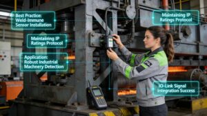
To objectively execute a flawless hardware integration, electrical engineers must deeply analyze the specific electromagnetic physics governing P+F inductive sensors. A standard inductive proximity switch operates utilizing a simple LC oscillator circuit, which generates a high-frequency alternating magnetic field localized at the sensing face. When a conductive object penetrates this field, eddy currents are induced within the target material. These currents drain kinetic energy from the oscillator, attenuating its amplitude. A threshold circuit detects this voltage drop and commutes the output signal. However, this standard physics model possesses a critical flaw: ‘Reduction Factors.’
Because standard sensors are calibrated against mild steel (St37), non-ferrous metals drastically alter the induction efficiency. For instance, aluminum possesses a reduction factor of approximately 0.4. Consequently, a sensor rated for a 10mm detection range will only detect an aluminum target at 4mm. In complex machinery processing mixed metals, this variable detection range causes devastating timing errors. To completely eradicate this physical limitation, Pepperl+Fuchs engineered ‘Reduction Factor 1’ technology. Rather than relying on a single ferrite core coil, Factor 1 sensors deploy a highly complex, multi-coil micro-controller architecture.
This advanced topology mathematically balances independent transmitter and receiver coils. The internal microprocessor actively analyzes the phase shift and amplitude of the returning signal, instantly calculating and compensating for the specific metallurgical composition of the target. As a result, the sensor detects steel, aluminum, brass, and copper at the exact same, uncompromising distance. This mathematical precision fundamentally guarantees that high-speed robotic cells can transition between processing distinct alloy components without requiring engineers to physically recalibrate or remount the sensing infrastructure.
Applications in Heavy Industrial Mining and Metallurgy
The strategic deployment of environmentally hardened sensors is aggressively dictated by the absolute severity of the deployment zone. Consider the massive, automated mineral extraction and metallurgical processing hubs situated in Guizhou, China. These advanced industrial corridors operate massive rock crushers, high-temperature smelting furnaces, and heavy automated guided vehicles (AGVs) operating in environments saturated with highly conductive coal dust and liquid coolant. Consequently, deploying standard proximity hardware in these zones guarantees immediate sensor blinding or physical housing destruction.
Furthermore, in the high-amperage robotic welding cells utilized within these heavy industrial sectors, ambient Electromagnetic Interference (EMI) reaches catastrophic levels. Consequently, the magnetic fields generated by a 10,000-amp spot welder will instantly induce false triggers in a standard LC oscillator circuit. Therefore, facility engineers strictly mandate the deployment of specialized weld-proof sensors. These specific components feature robust PTFE (Teflon) coatings to repel incandescent weld slag, and they utilize coreless coil designs that are mathematically immune to external AC/DC magnetic field saturation.
Consequently, in the physical crushing and sorting stages of Guizhou’s mining operations, sensing faces are subjected to relentless physical impact from stray ore and mechanical vibration. Therefore, engineers deploy ‘All-Metal Face’ (Pile Driver) sensors. Unlike standard sensors that utilize a fragile plastic or epoxy sensing face to permit magnetic field propagation, these sensors are machined from a single, continuous piece of thick stainless steel. Furthermore, the specialized internal coil is powerful enough to project the magnetic field directly through the steel housing. Therefore, this proprietary architecture mathematically eliminates the possibility of the sensing face shattering under mechanical impact, securing continuous, high-margin extraction throughput while completely isolating the facility from catastrophic hardware failures.
Comparison Matrix: Proximity Sensor Architectures
To objectively evaluate the structural and kinematic viability of varying detection architectures during a facility upgrade, procurement engineers must critically analyze comparative environmental data. The following matrix mathematically contrasts core inductive sensing topologies based on their physical resilience, target consistency, and ideal deployment environments:
| Sensor Architecture | Target Material Consistency | Physical Impact & Slag Resistance | EMI / Weld Field Immunity | Optimal Industrial Application |
| Standard Cylindrical (Plastic Face) | Variable. Suffers from severe reduction factors (Aluminum detected at 40% range). | Low. Plastic face shatters upon direct mechanical impact with heavy targets. | Poor. Highly susceptible to false triggers near VFDs and welding cells. | Clean environments, basic packaging lines, and light-duty material handling. |
| Reduction Factor 1 | Absolute. Detects Steel, Aluminum, Copper, and Brass at the exact same distance. | Moderate. Utilizes standard housings but offers supreme electronic stability. | High. Inherent multi-coil design resists ambient electromagnetic noise. | Mixed-metal CNC machining, automotive assembly, and flexible robotic cells. |
| Weld-Immune (PTFE Coated) | Variable (unless combined with Factor 1 tech). | High. PTFE coating repels incandescent weld spatter and prevents slag build-up. | Supreme. Coreless coil design cannot be saturated by high-amperage welding. | Robotic spot welding, MIG/TIG automation cells, and heavy fabrication. |
| All-Metal Face (Stainless Steel) | Variable (requires specific tuning to project through the steel face). | Supreme. Machined from a single block of steel; withstands direct, heavy impacts. | Moderate to High. Thick steel casing inherently provides excellent Faraday shielding. | Heavy mining, rock crushers, hydraulic presses, and extreme vibration zones. |
Execution Best Practices & Specs
Executing a structurally flawless detection matrix requires absolute adherence to rigorous mechanical and electrical parameters. The most critical operational concept an engineer must manage is ‘hysteresis.’ Hysteresis is the mathematical differential between the sensor’s exact operating point (when the target approaches and turns the sensor ON) and its release point (when the target departs and the sensor turns OFF). If a target is mechanically vibrating exactly at the operating threshold, a sensor with low hysteresis will rapidly toggle ON and OFF, inducing severe ‘chattering’ logic faults within the PLC. Engineers must rigorously calculate the mechanical vibration tolerances of the machine and specify industrial automation parts with sufficient hysteresis to guarantee absolute signal stability.
[Image detailing a hysteresis curve graph: illustrating the spatial differential between the switch-on point and switch-off point of a proximity sensor]
Furthermore, structural parameters dictate that switching frequency (measured in Hertz) must be meticulously aligned with the kinetic velocity of the target. A common engineering error occurs when extending the sensing range. As the physical size of the internal coil increases to project a larger magnetic field, the time required to collapse and rebuild that field mathematically increases. Consequently, a small 4mm range sensor may boast a switching frequency of 2000 Hz, while a massive 40mm range sensor may only achieve 100 Hz. In high-speed gear-tooth counting applications, selecting the larger sensor will result in catastrophic missed counts.
Finally, operators must strictly adhere to the geometric mounting protocols regarding ‘flush’ versus ‘non-flush’ installations. A non-flush sensor lacks lateral electromagnetic shielding; if it is embedded directly into a steel machine frame, the frame itself will instantly and permanently latch the sensor into the ON state. Engineers must calculate and machine a precise ‘free zone’ around the sensor head to ensure the magnetic field only interacts with the intended kinetic target. By combining these rigorous installation physics with intelligent procurement through Enicstra, technicians guarantee zero-fault detection across their entire automated fleet.
Frequently Asked Questions (FAQ)
- What is the fundamental operational advantage of Reduction Factor 1 technology?
Factor 1 technology completely eliminates the ‘reduction factor’ inherent in standard inductive sensors. It utilizes a complex multi-coil design to detect ferrous metals (steel) and non-ferrous metals (aluminum, brass, copper) at the exact same physical distance. This mathematically prevents machine crashes when an automated line transitions between processing different alloy components.
- How do ATEX zone ratings apply to proximity switches in mining and chemical sectors?
In environments containing highly explosive gas or combustible dust (such as coal mining or grain milling), sensors must carry strict ATEX or IECEx certifications. These NAMUR-rated sensors operate on exceptionally low voltage and current levels. They mathematically restrict the electrical energy stored within the circuit, ensuring that even in the event of a severed cable, the resulting spark lacks the thermal energy required to ignite the explosive atmosphere.
- Can I integrate Pepperl+Fuchs proximity sensors directly with IO-Link master blocks?
Yes. Modern intelligent sensors feature native IO-Link compatibility. While they can function as standard digital ON/OFF switches (SIO mode), wiring them into an IO-Link master unlocks deep diagnostic capabilities. The PLC can digitally read the internal temperature of the sensor, monitor signal quality degradation before a failure occurs, and remotely re-parameterize the sensor’s switching logic without manual intervention.
- What is the operational purpose of an ‘All-Metal Face’ (Pile Driver) inductive sensor?
Standard sensors use a plastic or epoxy face to allow the magnetic field to escape the housing. In highly abrasive environments where flying metal chips or heavy mechanical impacts occur, this plastic shatters. An All-Metal Face sensor is machined from a single, thick piece of stainless steel. It is engineered to withstand brutal physical punishment while still projecting its magnetic field through the steel barrier.
- How does a weld-immune sensor physically survive constant incandescent slag bombardment?
Weld-immune sensors utilize two primary defensive architectures. Physically, the brass or stainless housing is heavily coated in PTFE (Teflon), preventing molten weld spatter from adhering to the sensor face. Electronically, they utilize a coreless coil design that is mathematically immune to the massive AC/DC magnetic fields generated by the welding electrodes, preventing false-positive triggers during the weld cycle.
- Why does the maximum switching frequency decrease when I select a sensor with a longer detection range?
This is governed by electromagnetic physics. To achieve a longer detection range, the sensor requires a physically larger copper coil and a larger ferrite core to project the field further. It mathematically takes more time to energize, collapse, and process the eddy current feedback of this massive magnetic field. Therefore, long-range sensors have inherently slower recovery times (lower Hz) than micro-sensors.
Conclusion
The engineering reality within the high-stakes, hyper-abrasive manufacturing landscape is mathematically irrefutable: attempting to secure a heavy industrial robotic cell or automated metallurgical facility utilizing standard, unprotected commercial sensors guarantees catastrophic mechanical collisions, continuous signal faults, and severe financial bleed. By migrating your detection architecture directly to specialized capacitive proximity switch and inductive technologies, you permanently mathematicalize your facility’s kinetic precision and mechanical resilience. We guarantee absolute resistance to weld-field interference, eradicate the threat of physical housing destruction, and unlock rapid, deterministic accuracy for your entire production line.
Do not compromise your facility’s machining tolerances and physical safety by relying on degraded hardware and unverified detection protocols. Secure the structural integrity of your entire industrial network by upgrading your sensing capabilities today. Access our massive inventory of verified automation hardware to instantly acquire high-precision Pepperl+Fuchs sensors, deploy flawless Factor 1 integrations, and fundamentally revolutionize your global motion control trajectory. Secure your absolute detection precision today.
