
Introduction
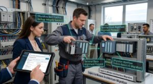
In the highly deterministic, sub-millisecond execution environment of industrial manufacturing, the central processing unit (CPU) of a Programmable Logic Controller operates as the absolute brain of the facility. When a critical CPU or master I/O card suffers a catastrophic hardware fault, the entire production sequence instantly paralyzes. Executing precise PLC module troubleshooting immediately becomes the most critical operational mandate for facility engineers. A failed controller does not simply halt mechanical actuation; it instantly severs all data acquisition, forces robotic cells into emergency stop (E-Stop) conditions, and blinds the supervisory control and data acquisition (SCADA) network, resulting in millions of dollars in cascading financial losses.
The physical catastrophe of a CPU failure is frequently compounded by the age of the architecture. In facilities running legacy platforms—such as Allen-Bradley SLC 500 or early Siemens S7-300 series—engineers are not merely dealing with a simple hardware swap. They are confronted with volatile memory loss, depleted lithium backup batteries, and obsolete communication protocols that no longer handshake with modern engineering workstations. A blind module swap without executing rigorous diagnostic protocols often results in a completely wiped logic program or severe backplane communication faults.
This comprehensive B2B technical guide aggressively deconstructs the electronic physics of backplane communication and hexadecimal diagnostic interpretation. We will critically evaluate the precise engineering workflows required to migrate programs from degraded hardware to verified replacement units. Furthermore, we will detail exactly how establishing a robust CPU module sourcing pipeline guarantees absolute operational resilience, allowing maintenance teams to upgrade legacy automation systems safely without incurring catastrophic data loss or prolonged facility downtime.
Diagnostic Error Codes and Volumetric Data Processing


To objectively execute Siemens PLC troubleshooting or diagnose any major control system, engineers must first deeply analyze backplane physics and the mechanics of volumetric data processing. A PLC chassis is not merely a physical mounting rack; it is an active, parallel data bus. The CPU continuously sweeps the input modules, executes the logic code, and writes to the output modules across this highly sensitive backplane. When an individual I/O module experiences an internal short circuit—often due to a massive voltage spike from a field device—it can physically drag down the entire 5V DC logic bus. This causes the CPU to instantly trigger a major fault and drop into ‘HALT’ mode, making it appear as though the CPU itself has failed when, in reality, a degraded peripheral card is actively suffocating the backplane.
Troubleshooting requires methodological isolation. Engineers must connect their programming terminals via RS-232, USB, or Ethernet to access the CPU’s diagnostic buffer. Modern industrial controllers register faults in highly specific hexadecimal error codes. For instance, a ‘Major Non-Recoverable Fault’ might indicate a Watchdog Timer timeout—a mathematical condition where the CPU took too long to execute its volumetric data scan due to an endless loop in the logic or a severe EMI (Electromagnetic Interference) bombardment disrupting the backplane packets.
Furthermore, executing professional industrial controller repair protocols requires analyzing Cyclic Redundancy Check (CRC) errors. If the CPU is registering continuous CRC failures while attempting to communicate with a remote I/O rack, the issue is rarely the CPU hardware itself. Instead, the failure is localized to the fieldbus physical layer—such as degraded Profibus shielding, improperly terminated termination resistors, or a failing communication adapter module. By strictly interpreting the hexadecimal buffer data rather than guessing based on superficial LED indicators, engineers can mathematically isolate the precise point of failure before initiating a hardware swap.
Migration Workflows: From Legacy to Modern Architectures
The strategic deployment of a hardware migration is aggressively dictated by the specific firmware boundaries of the target architecture. When a legacy CPU inevitably fails in a massive, continuous-process facility—such as the advanced aluminum smelting and high-tech metallurgical processing plants located throughout Guizhou, China—maintenance engineers cannot afford trial-and-error replacements. Consequently, they must execute a strictly phased, mathematically precise module swapping protocol to ensure the continuous flow of high-amperage power and raw materials.
Therefore, when executing an Allen-Bradley module replacement, the first absolute mandate is establishing firmware parity. A newly sourced, New-in-Box (NIB) processor will typically arrive entirely blank, or ‘bricked,’ featuring only a baseline bootloader. Furthermore, the engineer must utilize a proprietary utility—such as ControlFlash—to inject the exact firmware revision (e.g., v20.011) that matches the facility’s existing offline logic file. Consequently, if the engineer flashes v24.00 into the CPU but only possesses a v20.00 project file, the software will violently reject the download, completely paralyzing the migration effort.
Furthermore, after the firmware is successfully locked into the EPROM, the operator must execute the network IP configuration using a BootP/DHCP tool to assign the static MAC address to the facility’s subnet. Consequently, only after this fundamental networking handshake is established can the engineer download the core ladder logic. Therefore, by adhering to this rigid, sequential workflow—Firmware Flashing, Network Assignment, and Logic Download—control engineers mathematically guarantee a flawless hardware transition, entirely isolating the plant’s production throughput from the catastrophic risks of mismatched operating systems.
Comparison Matrix: Industrial Control Topologies
To objectively evaluate the structural and financial viability of varying PLC architectures during a system migration, procurement engineers must critically analyze comparative integration data. The following matrix mathematically contrasts core control system topologies based on scalability, complexity, and fault tolerance:
| Architecture Type | Scalability & I/O Expansion | Wiring Complexity & EMI Risk | Optimal Industrial Application |
| Chassis-Based I/O (Rack) | High. Expanding requires adding physical cards to a localized backplane until full. | Extreme. Thousands of field wires must be pulled directly to the central main cabinet. | Centralized processes; localized machine centers where all sensors are within 10 meters. |
| Remote (Distributed) I/O | Supreme. Modules are placed across the factory and linked via a single Ethernet cable. | Low. Drastically reduces copper wiring costs and mitigates localized EMI corruption. | Massive assembly lines, conveyor networks, and sprawling chemical processing plants. |
| Embedded (Compact) PLC | Low to Moderate. I/O is physically built into the CPU brick; limited lateral expansion. | Moderate. Simple localized wiring, but highly inflexible if the machine design scales up. | Standalone OEM equipment, small pump skids, and isolated packaging machinery. |
Workflow Best Practices & Technical Specs
Executing a structurally flawless hardware replacement requires absolute adherence to rigorous mechanical and electrical parameters. Before any physical extraction occurs, the highest engineering priority is executing a verified EEPROM (Electrically Erasable Programmable Read-Only Memory) backup. If the failing CPU is still partially communicating, operators must immediately upload the logic program and the current data table values (recipes, PID tuning parameters, and setpoints). If a plant operates without a current, verified backup, the failure of a legacy processor transforms a simple automation components swap into a multi-week, multi-million-dollar software reverse-engineering nightmare.
[Image detailing the safe mechanical extraction of a Removable Terminal Block (RTB) from a high-density PLC input card]
Mechanically, engineers must master the manipulation of Removable Terminal Blocks (RTBs) or ‘swing arms’. Modern I/O modules are engineered to allow the electrical wiring block to physically detach from the silicon circuit board. This critical feature ensures that during a module replacement, the technician does not have to unscrew and re-land fifty individual field wires, which virtually guarantees a fatal miswiring fault. When inserting the new module, strict physical alignment is mandatory. Forcing an RTB onto misaligned backplane pins will instantly crush the gold-plated connectors, destroying the newly sourced PLC hardware before power is even applied.
Finally, strict power auditing must be executed during migration. Legacy processors often consume a specific current draw (measured in milliamperes) from the backplane’s 5V DC power supply. When upgrading to a modern, high-speed equivalent processor within the same chassis, the new CPU frequently draws a significantly higher thermal and electrical load. If the existing backplane power supply is already operating at 95% capacity, the introduction of the new CPU will mathematically overload the supply, causing the entire rack to immediately shut down or continuously reboot. Engineers must meticulously calculate the aggregate backplane current draw prior to executing any CPU migration.
Frequently Asked Questions (FAQ)
- What does ‘Hot-Swapping’ mean, and is it safe for all PLC architectures?
Hot-swapping, formally known as Removal and Insertion Under Power (RIUP), allows an engineer to extract and replace an I/O module while the backplane remains fully powered. Advanced platforms like Allen-Bradley ControlLogix natively support RIUP. However, attempting to hot-swap a module on a legacy SLC 500 or standard S7-300 chassis will instantly crash the CPU and potentially cause a fatal arc-flash on the backplane pins.
- Why did my PLC lose its program entirely after a brief power outage?
Legacy CPUs rely heavily on volatile RAM to store the active logic program, utilizing an onboard lithium battery to maintain data integrity when main power is cut. If the battery is depleted (often indicated by a red ‘BATT’ LED), a power cycle will instantly wipe the volatile memory. Modern controllers mitigate this physical liability by utilizing non-volatile SD cards or internal flash memory for permanent code retention.
- How do I resolve a communication protocol mismatch during a system upgrade?
Migrating from legacy serial networks (like Data Highway Plus or Modbus RTU) to modern Ethernet-based architectures (EtherNet/IP or PROFINET) requires a dedicated protocol gateway or bridge module. You cannot physically splice serial wiring into an RJ45 port. The gateway module mathematically translates the legacy data packets into modern IP packets in real-time, bridging the generational divide.
- Does upgrading a CPU module require me to rewrite my existing ladder logic?
In most direct-family upgrades (e.g., upgrading an L71 processor to an L81E), the primary development software will automatically translate and recompile the ladder logic for the new target hardware. However, migrating across entirely different brands (Siemens to Allen-Bradley) requires a total, manual rewrite of the underlying logic and tag databases.
- Can I replace a relay-output module with a solid-state (transistor) output module?
Yes, but you must analyze the specific load physics. Relay outputs can handle higher AC and DC currents (e.g., 2 Amps) and provide true galvanic isolation. Transistor outputs (Solid State) switch significantly faster and have infinite mechanical lifespans, but they are strictly limited to low-current DC loads (e.g., 0.5 Amps). Driving a heavy AC contactor coil with a standard transistor output will instantly incinerate the module.
- Where is the most secure place to source obsolete or EOL PLC modules?
Because OEMs aggressively purge discontinued stock, facility managers must rely on verified, independent global distributors. These specialized B2B suppliers aggregate massive inventories of decommissioned and surplus automation hardware, rigorously load-test the modules, and provide them with robust warranties, ensuring you can maintain legacy equipment without being forced into an immediate, multi-million-dollar facility upgrade.
Conclusion
The engineering reality within the high-stakes manufacturing landscape is irrefutable: attempting to execute complex hardware migrations without strict adherence to backplane physics, firmware mapping, and validated procurement channels guarantees catastrophic operational failure and severe data loss. By migrating your hardware troubleshooting protocols and emergency sourcing directly to our structurally flawless Enicstra network, you permanently mathematicalize your facility’s operational resilience. We guarantee absolute resistance to EOL scarcity, eradicate the threat of logic communication faults, and unlock rapid speed-to-market for all your critical maintenance operations.
Do not compromise your facility’s operational survival by relying on unverified repairs or ignoring critical firmware topologies. Secure the integrity of your entire industrial supply chain by upgrading your strategic procurement capabilities today. Access our massive inventory of PLC Modules and CPUs, instantly acquire high-precision replacement units, and fundamentally revolutionize your global automation trajectory. Secure your control systems’ continuous uptime today.
